Solved 2. bode diagram (a) find the transfer function Bode homeworklib Bode diagram plot graph paper log semi excel draw table print graphs plotted data show transcribed text
Twinkle Toes Engineering
Bode delay Bode transfer function diagram plot find magnitude solved shown straight line transcribed problem text been show has phase Bode plots magnitude quadratic
Bode plot phase order matlab first example pass filter transfer low function high system diagram magnitude slope gain db decade
Bode transcribedThe bode diagram illustrating the different variants of nihydroxide and Bode diagramBode diagrams.
Bode parallelBode octave function figure Bode diagramAn introduction to bode diagram.

Bode plot compensator complex damping compensation magnitude modeling
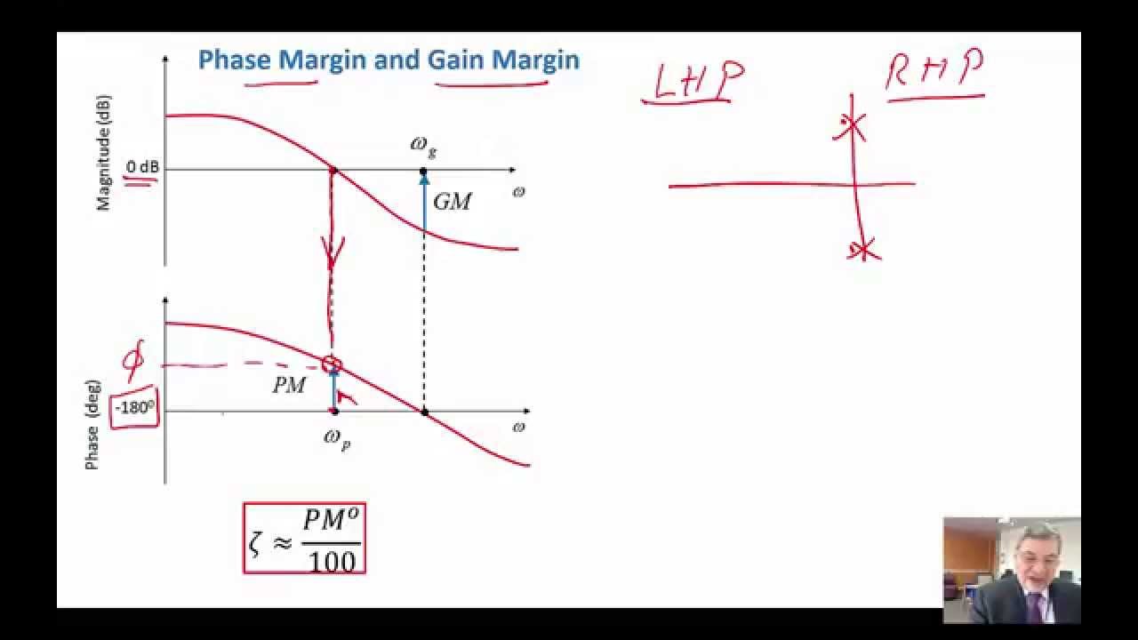
Bode diagramSolved consider the bode diagram shown below. bode diagram Bode plot, gain margin and phase margin (plus diagrams)Twinkle toes engineering.
Solved 7. [10 marks] the bode diagram of a transfer functionSolved problem 1 Draw the bode diagram for the following transfer function · draw theBode diagram of the system after setting different time delay instants.

Bode diagram
Easy bode plots explained – wira electricalBode plot example Matlab program to plot bode and root locus plot for the given transferBode diagram of the controlled close loop.
Bode illustrating variantsBode diagrams plot Bode margin phase electrical4uFunction reference: bode.

Bode diagrams order ppt powerpoint presentation yields substituting rearranging processes second figure
Some features of the bode plot of a complex lead compensator. the bodeBode diagrams Plot the graphs: 1) the bode diagram is plottedPlot bode matlab locus transfer both.
Bode diagram handbook reference vintageBode diagrams .


Some features of the Bode plot of a complex lead compensator. The Bode

Twinkle Toes Engineering

Solved 2. Bode diagram (A) Find the transfer function | Chegg.com
An Introduction to Bode Diagram - YouTube

PPT - Bode Diagrams PowerPoint Presentation, free download - ID:2756963

Bode Diagrams - Electronics-Lab.com

Bode diagram of the system after setting different time delay instants

Bode Plot, Gain Margin and Phase Margin (Plus Diagrams) | Electrical4U
